
 Introduction
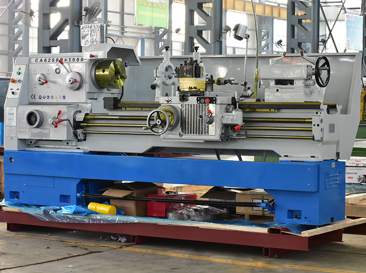
Ordinary lathes are horizontal lathes that can process various types of workpieces such as shafts, discs, rings, etc. Drilling, reaming, tapping and knurling, etc.
structure function
The main components of the ordinary lathe are: headstock, feed box, slide box, tool rest, tailstock, smooth screw, lead screw and bed.
Headstock: Also known as headstock, its main task is to pass the rotational motion from the main motor through a series of speed change mechanisms so that the main shaft can obtain the required different speeds of forward and reverse steering, and at the same time the headstock separates part of the power Pass motion to the feed box. Headstock Medium spindle is a key part of the lathe. The smoothness of the spindle running on the bearing directly affects the processing quality of the workpiece. Once the rotation accuracy of the spindle is reduced, the use value of the machine tool will be reduced.
Feed box: Also known as the tool box, the feed box is equipped with a speed change mechanism for feeding motion. Adjust the speed change mechanism to obtain the required feed amount or pitch, and transmit the motion to the knife through a smooth screw or lead screw. rack for cutting.
Lead screw and smooth screw: used to connect the feeding box and the sliding box, and transmit the motion and power of the feeding box to the sliding box, so that the sliding
live top
The crate obtains longitudinal linear motion. The lead screw is specially used for turning various threads. When turning other surfaces of the workpiece, only the smooth screw is used, and the lead screw is not used.
Slide box: It is the control box for the feeding movement of the lathe. It is equipped with a mechanism that converts the rotary motion of the light bar and the lead screw into the linear motion of the tool rest. The longitudinal feed motion and transverse feed motion of the tool rest are realized through the light bar transmission. And rapid movement, through the screw to drive the tool holder to make longitudinal linear motion, so as to turn the thread.
Tool holder: The tool holder is composed of several layers of tool holders. Its function is to clamp the tool and make the tool move longitudinally, laterally or obliquely.
Tailstock: Install the rear center for positioning support, and can also install hole processing tools such as drills and reamers for hole processing.
Bed: The main parts of the lathe are installed on the bed, so that they maintain an accurate relative position during work.
appendix
1. Three-jaw chuck (for cylindrical workpieces), four-jaw chuck (for irregular workpieces)
2. Live center (for fixing workpieces)
3. Center frame (stable workpiece)
4. With the knife holder
main feature
1. Large torque at low frequency and stable output
2. High-performance vector control
3. Fast dynamic torque response and high speed stabilization accuracy
4. Slow down and stop fast
5. Strong anti-interference ability
Operating procedures
1. Inspection before driving
1.1 Add appropriate grease according to the machine lubrication chart.
1.2 Check all electrical facilities, handle, transmission parts, protection and limit devices are complete, reliable and flexible.
1.3 Each gear should be at zero position, and the belt tension should meet the requirements.
1.4 It is not allowed to store metal objects directly on the bed, so as not to damage the bed.
1.5 The workpiece to be processed is free of mud and sand, preventing mud and sand from falling into the pallet and wearing out the guide rail.
1.6 Before the workpiece is clamped, an empty car test run must be carried out. After confirming that everything is normal, the workpiece can be loaded.
2. Operating procedures
2.1 After the workpiece is installed, start the lubricating oil pump first to make the oil pressure meet the requirements of the machine tool before starting.
2.2 When adjusting the exchange gear rack, when adjusting the hanging wheel, the power supply must be cut off. After the adjustment, all bolts must be tightened, the wrench should be removed in time, and the workpiece should be disconnected for trial operation.
2.3 After loading and unloading the workpiece, the chuck wrench and floating parts of the workpiece should be removed immediately.
2.4 The tailstock, crank handle, etc. of the machine tool shall be adjusted to appropriate positions according to the processing needs, and shall be tightened or clamped.
2.5 Workpieces, tools and fixtures must be securely mounted. The floating force tool must extend the lead-in part into the workpiece before starting the machine tool.
2.6 When using the center rest or the tool rest, the center must be adjusted well, and there must be good lubrication and supporting contact surfaces.
2.7 When processing long materials, the protruding part behind the main shaft should not be too long.
2.8 When feeding the knife, the knife should approach the work slowly to avoid collision; the speed of the carriage should be uniform. When changing the tool, the tool and the workpiece must maintain a proper distance.
2.9 The cutting tool must be fastened, and the extension length of the turning tool generally does not exceed 2.5 times the thickness of the tool.
2.1.0 When machining eccentric parts, there must be proper counterweight to balance the center of gravity of the chuck, and the speed of the vehicle should be appropriate.
2.1.1. There must be protective measures for the workpieces that go beyond the fuselage.
2.1.2 The adjustment of the tool setting must be slow. When the tool tip is 40-60 mm away from the processing part of the workpiece, manual or working feed should be used instead, and rapid feed is not allowed to directly engage the tool.
2.1.3 When polishing the workpiece with a file, the tool holder should be retracted to a safe position, and the operator should face the chuck, with the right hand in front and the left hand behind. There is a keyway on the surface, and the workpiece with a square hole is not allowed to be processed with a file.
2.1.4 When polishing the outer circle of the workpiece with emery cloth, the operator should hold the two ends of the emery cloth with both hands to polish according to the posture specified in the previous article. It is forbidden to use your fingers to hold the abrasive cloth to polish the inner hole.
2.1.5 During automatic knife feeding, the small knife holder should be adjusted to be flush with the base to prevent the base from touching the chuck.
2.1.6 When cutting large and heavy workpieces or materials, sufficient machining allowance should be reserved.
3. Parking operation
3.1 Cut off the power and remove the workpiece.
3.2 The handles of each part are knocked down to the zero position, and the tools are counted and cleaned.
3.3 Check the condition of each protection device.
4. Precautions during operation
4.1 It is strictly forbidden for non-workers to operate the machine.
4.2 It is strictly forbidden to touch the tool, the rotating part of the machine tool or the rotating workpiece during operation.
4.3 It is not allowed to use emergency stop. In case of emergency, after using this button to stop, it should be checked again according to the regulations before starting the machine tool.
4.4 It is not allowed to step on the guide rail surface, screw rod, polished rod, etc. of the lathe. Except for the regulations, it is not allowed to operate the handle with feet instead of hands.
4.5 For parts with blisters, shrinkage holes or keyways on the inner wall, triangular scrapers are not allowed to cut the inner holes.
4.6 The compressed air or liquid pressure of the pneumatic rear hydraulic chuck must reach the specified value before it can be used.
4.7 When turning slender workpieces, when the protruding length of the front two sides of the head of the bed is more than 4 times the diameter, the center should be used according to the process regulations. Center rest or heel rest support. Guards and warning signs should be added when protruding behind the head of the bed.
4.8 When cutting brittle metals or cutting easily splashed (including grinding), protective baffles should be added, and operators should wear protective glasses.
Conditions of Use
The normal use of ordinary lathes must meet the following conditions: the power supply voltage fluctuation at the location of the machine tool is small, the ambient temperature is lower than 30 degrees Celsius, and the relative humidity is less than 80%.
1. Environmental requirements for the location of the machine tool
The location of the machine tool should be far away from the vibration source, direct sunlight and thermal radiation should be avoided, and the influence of humidity and airflow should be avoided. If there is a vibration source near the machine tool, anti-vibration grooves should be set around the machine tool. Otherwise, it will directly affect the machining accuracy and stability of the machine tool, which will cause poor contact of the electronic components, failure, and affect the reliability of the machine tool.
2. Power requirements
Generally, ordinary lathes are installed in the machining workshop, not only the ambient temperature changes greatly, the use conditions are poor, but also there are many kinds of electromechanical equipment, resulting in large fluctuations in the power grid. Therefore, the location where ordinary lathes are installed requires strict control of the power supply voltage. Power supply voltage fluctuations must be within the allowable range and remain relatively stable. Otherwise, the normal operation of the CNC system will be affected.
3. Temperature conditions
The ambient temperature of ordinary lathes is lower than 30 degrees Celsius, and the relative temperature is less than 80%. Generally speaking, there is an exhaust fan or a cooling fan inside the CNC electric control box to keep the working temperature of the electronic components, especially the central processing unit, constant or the temperature difference changes very little. Excessive temperature and humidity will reduce the life of control system components and lead to increased failures. The increase of temperature and humidity, and the increase of dust will cause bonding on the integrated circuit board and cause short circuit.
4. Use the machine tool as specified in the manual
When using the machine tool, the user is not allowed to change the parameters set by the manufacturer in the control system at will. The setting of these parameters is directly related to the dynamic characteristics of each component of the machine tool. Only the backlash compensation parameter values can be adjusted according to the actual situation.
The user cannot change the accessories of the machine tool at will, such as using the hydraulic chuck beyond the specification. The manufacturer fully considers the matching of various link parameters when setting accessories. Blind replacement results in mismatch of parameters in various links, and even causes unexpected accidents. The pressure of the hydraulic chuck, hydraulic tool rest, hydraulic tailstock and hydraulic cylinder should be within the allowable stress range, and it is not allowed to increase arbitrarily.
Post time: Sep-09-2022