
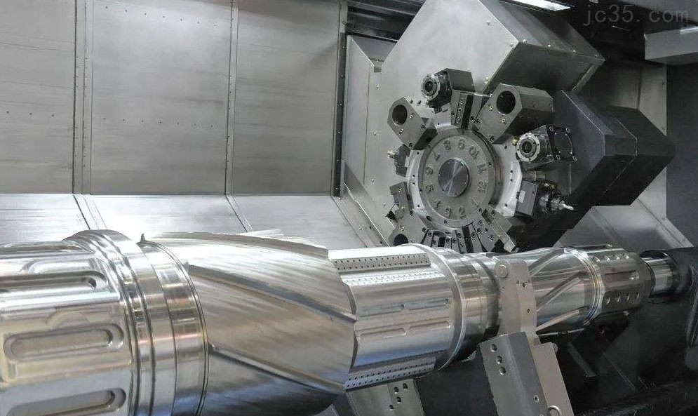
TURNING
During turning, the workpiece rotates to form the main cutting motion. When the tool moves along the parallel axis of rotation, the inner and outer cylindrical surfaces are formed. The tool moves along an oblique line intersecting the axis to form a conical surface. On a profiling lathe or a CNC lathe, the tool can be controlled to feed along a curve to form a specific surface of revolution. Using a forming turning tool, the rotating surface can also be processed during lateral feed. Turning can also process thread surfaces, end planes and eccentric shafts. The turning accuracy is generally IT8-IT7, and the surface roughness is 6.3-1.6μm. When finishing, it can reach IT6-IT5, and the roughness can reach 0.4-0.1μm. Turning has higher productivity, smoother cutting process and simpler tools.
MILLING
The main cutting motion is the rotation of the tool. During horizontal milling, the formation of the plane is formed by the edge on the outer surface of the milling cutter. In end milling, the plane is formed by the end face edge of the milling cutter. Increasing the rotation speed of the milling cutter can achieve higher cutting speeds and therefore higher productivity. However, due to the cut-in and cut-out of the milling cutter teeth, the impact is formed, and the cutting process is prone to vibration, thus limiting the improvement of the surface quality. This impact also aggravates the wear and tear of the tool, which often leads to the chipping of the carbide insert. In the general time when the workpiece is cut off, a certain amount of cooling can be obtained, so the heat dissipation conditions are better. According to the same or opposite direction of the main movement speed and workpiece feed direction during milling, it is divided into down milling and up milling.
1. Climb milling
The horizontal component force of the milling force is the same as the feed direction of the workpiece. Generally, there is a gap between the feed screw of the workpiece table and the fixed nut. Therefore, the cutting force can easily cause the workpiece and the table to move forward together, causing the feed rate to be sudden. increase, causing a knife. When milling workpieces with hard surfaces such as castings or forgings, the teeth of the down milling cutter first contact the hard skin of the workpiece, which aggravates the wear of the milling cutter.
2. Up milling
It can avoid the movement phenomenon that occurs during down milling. During up-cut milling, the thickness of the cut increases gradually from zero, so the cutting edge begins to experience a period of squeezing and sliding on the cut-hardened machined surface, accelerating tool wear. At the same time, during up milling, the milling force lifts the workpiece, which is easy to cause vibration, which is the disadvantage of up milling.
The machining accuracy of milling can generally reach IT8-IT7, and the surface roughness is 6.3-1.6μm.
Ordinary milling can generally only process flat surfaces, and forming milling cutters can also process fixed curved surfaces. The CNC milling machine can use software to control several axes to be linked according to a certain relationship through the CNC system to mill out complex curved surfaces. At this time, a ball-end milling cutter is generally used. CNC milling machines are of particular significance for machining workpieces with complex shapes such as blades of impeller machinery, cores and cavities of molds.
PLANING
When planing, the reciprocating linear motion of the tool is the main cutting motion. Therefore, the planing speed cannot be too high and the productivity is low. Planing is more stable than milling, and its machining accuracy can generally reach IT8-IT7, the surface roughness is Ra6.3-1.6μm, the precision planing flatness can reach 0.02/1000, and the surface roughness is 0.8-0.4μm.
GRINDING
Grinding processes the workpiece with a grinding wheel or other abrasive tools, and its main motion is the rotation of the grinding wheel. The grinding process of the grinding wheel is actually the combined effect of the three actions of the abrasive particles on the surface of the workpiece: cutting, engraving and sliding. During grinding, the abrasive particles themselves are gradually blunt from sharpness, which makes the cutting effect worse and the cutting force increases. When the cutting force exceeds the strength of the adhesive, the round and dull abrasive grains fall off, exposing a new layer of abrasive grains, forming the “self-sharpening” of the grinding wheel. But chips and abrasive particles can still clog the wheel. Therefore, after grinding for a certain period of time, it is necessary to dress the grinding wheel with a diamond turning tool.
When grinding, because there are many blades, the processing is stable and high precision. The grinding machine is a finishing machine tool, the grinding accuracy can reach IT6-IT4, and the surface roughness Ra can reach 1.25-0.01μm, or even 0.1-0.008μm. Another feature of grinding is that it can process hardened metal materials. Therefore, it is often used as the final processing step. During grinding, a large amount of heat is generated, and sufficient cutting fluid is required for cooling. According to different functions, grinding can also be divided into cylindrical grinding, internal hole grinding, flat grinding and so on.
DRILLING and BORING
On a drilling machine, rotating a hole with a drill bit is the most common method of hole machining. The machining accuracy of drilling is low, generally only reaching IT10, and the surface roughness is generally 12.5-6.3 μm. After drilling, reaming and reaming are often used for semi-finishing and finishing. The reaming drill is used for reaming, and the reaming tool is used for reaming. The reaming accuracy is generally IT9-IT6, and the surface roughness is Ra1.6-0.4μm. When reaming and reaming, the drill bit and reamer generally follow the axis of the original bottom hole, which cannot improve the positional accuracy of the hole. Boring corrects the position of the hole. Boring can be done on a boring machine or a lathe. When boring on a boring machine, the boring tool is basically the same as the turning tool, except that the workpiece does not move and the boring tool rotates. The boring machining accuracy is generally IT9-IT7, and the surface roughness is Ra6.3-0.8mm. .
Drilling Boring Lathe
TOOTH SURFACE PROCESSING
Gear tooth surface machining methods can be divided into two categories: forming method and generating method. The machine tool used to process the tooth surface by the forming method is generally an ordinary milling machine, and the tool is a forming milling cutter, which requires two simple forming movements: the rotational movement of the tool and the linear movement. The commonly used machine tools for processing tooth surfaces by generating method include gear hobbing machines and gear shaping machines.
COMPLEX SURFACE PROCESSING
The machining of three-dimensional curved surfaces mainly adopts the methods of copy milling and CNC milling or special processing methods (see Section 8). Copy milling must have a prototype as a master. During processing, the profiling head of the ball head is always in contact with the prototype surface with a certain pressure. The movement of the profiling head is transformed into inductance, and the processing amplification controls the movement of the three axes of the milling machine, forming the trajectory of the cutter head moving along the curved surface. The milling cutters mostly use ball end milling cutters with the same radius as the profiling head. The emergence of numerical control technology provides a more effective method for surface machining. When machining on a CNC milling machine or machining center, it is processed by a ball-end milling cutter according to the coordinate value point by point. The advantage of using a machining center to process complex surfaces is that there is a tool magazine on the machining center, equipped with dozens of tools. For roughing and finishing of curved surfaces, different tools can be used for different curvature radii of concave surfaces, and appropriate tools can also be selected. At the same time, various auxiliary surfaces such as holes, threads, grooves, etc. can be machined in one installation. This fully guarantees the relative positional accuracy of each surface.
SPECIAL PROCESSING
Special processing method refers to a general term for a series of processing methods that are different from traditional cutting methods and use chemical, physical (electricity, sound, light, heat, magnetism) or electrochemical methods to process workpiece materials. These machining methods include: chemical machining (CHM), electrochemical machining (ECM), electrochemical machining (ECMM), electrical discharge machining (EDM), electrical contact machining (RHM), ultrasonic machining (USM), laser beam machining ( LBM), Ion Beam Machining (IBM), Electron Beam Machining (EBM), Plasma Machining (PAM), Electro-Hydraulic Machining (EHM), Abrasive Flow Machining (AFM), Abrasive Jet Machining (AJM), Liquid Jet Machining (HDM) ) and various composite processing.
1. EDM
EDM is to use the high temperature generated by the instantaneous spark discharge between the tool electrode and the workpiece electrode to erode the surface material of the workpiece to achieve machining. EDM machine tools are generally composed of pulse power supply, automatic feeding mechanism, machine tool body and working fluid circulation filtering system. The workpiece is fixed on the machine table. The pulse power supply provides the energy required for processing, and its two poles are respectively connected to the tool electrode and the workpiece. When the tool electrode and the workpiece approach each other in the working fluid driven by the feeding mechanism, the voltage between the electrodes breaks down the gap to generate spark discharge and release a lot of heat. After the surface of the workpiece absorbs heat, it reaches a very high temperature (above 10000 ° C), and its local material is etched off due to melting or even gasification, forming a tiny pit. The working fluid circulation filtration system forces the cleaned working fluid to pass through the gap between the tool electrode and the workpiece at a certain pressure, so as to remove the galvanic corrosion products in time, and filter the galvanic corrosion products from the working fluid. As a result of multiple discharges, a large number of pits are produced on the surface of the workpiece. The tool electrode is continuously lowered under the drive of the feeding mechanism, and its contour shape is “copied” to the workpiece (although the tool electrode material will also be eroded, its speed is much lower than that of the workpiece material). EDM machine tool for machining corresponding workpieces with special-shaped electrode tools
① Processing hard, brittle, tough, soft and high melting point conductive materials;
②Processing semiconductor materials and non-conductive materials;
③ Process various types of holes, curved holes and tiny holes;
④ Process various three-dimensional curved cavities, such as forging dies, die-casting dies, and plastic dies;
⑤It is used for cutting, cutting, surface strengthening, engraving, printing nameplates and marks, etc.
Wire EDM Machine Tool for Machining 2D Profile Shaped Workpieces with Wire Electrodes
2. Electrolytic machining
Electrolytic machining is a method of forming workpieces using the electrochemical principle of anodic dissolution of metals in electrolytes. The workpiece is connected to the positive pole of the DC power supply, the tool is connected to the negative pole, and a small gap (0.1mm ~ 0.8mm) is maintained between the two poles. The electrolyte with a certain pressure (0.5MPa~2.5MPa) flows through the gap between the two poles at a high speed of 15m/s~60m/s). When the tool cathode is continuously fed to the workpiece, on the surface of the workpiece facing the cathode, the metal material is continuously dissolved according to the shape of the cathode profile, and the electrolysis products are taken away by the high-speed electrolyte, so the shape of the tool profile is correspondingly “copied” ” on the workpiece.
①The working voltage is small and the working current is large;
② Process a complex-shaped profile or cavity at one time with a simple feed motion;
③ It can process difficult-to-process materials;
④ High productivity, about 5 to 10 times that of EDM;
⑤ There is no mechanical cutting force or cutting heat during processing, which is suitable for the processing of easily deformed or thin-walled parts;
⑥The average machining tolerance can reach about ±0.1mm;
⑦ There are many auxiliary equipment, covering a large area and high cost;
⑧The electrolyte not only corrodes the machine tool, but also easily pollutes the environment. Electrochemical machining is mainly used for processing holes, cavities, complex profiles, small diameter deep holes, rifling, deburring, and engraving.
3. Laser processing
The laser processing of the workpiece is completed by a laser processing machine. Laser processing machines are usually composed of lasers, power supplies, optical systems and mechanical systems. Lasers (commonly used solid-state lasers and gas lasers) convert electrical energy into light energy to generate the required laser beams, which are focused by an optical system and then irradiated on the workpiece for processing. The workpiece is fixed on the three-coordinate precision worktable, which is controlled and driven by the numerical control system to complete the feed movement required for processing.
①No machining tools are required;
②The power density of the laser beam is very high, and it can process almost any metal and non-metal materials that are difficult to process;
③ Laser processing is non-contact processing, and the workpiece is not deformed by force;
④The speed of laser drilling and cutting is very high, the material around the processing part is hardly affected by the cutting heat, and the thermal deformation of the workpiece is very small.
⑤ The slit of laser cutting is narrow, and the cutting edge quality is good. Laser processing has been widely used in diamond wire drawing dies, watch gem bearings, porous skins of divergent air-cooled punches, small hole processing of engine fuel injection nozzles, aero-engine blades, etc., as well as cutting of various metal materials and non-metal materials. .
4. Ultrasonic processing
Ultrasonic machining is a method in which the end face of the tool vibrating with ultrasonic frequency (16KHz ~ 25KHz) impacts the suspended abrasive in the working fluid, and the abrasive particles impact and polish the surface of the workpiece to realize the machining of the workpiece. The ultrasonic generator converts the power frequency AC electrical energy into ultrasonic frequency electrical oscillation with a certain power output, and converts the ultrasonic frequency electrical oscillation into ultrasonic mechanical vibration through the transducer. ~0.01mm is enlarged to 0.01~0.15mm, driving the tool to vibrate. The end face of the tool impacts the suspended abrasive particles in the working fluid in the vibration, so that it continuously hits and polishes the surface to be machined at a high speed, and crushes the material in the processing area into very fine particles and hits it down. Although there is very little material in each blow, there is still a certain processing speed due to the high frequency of blows. Due to the circulating flow of the working fluid, the material particles that have been hit are taken away in time. As the tool is progressively inserted, its shape is “copied” onto the workpiece.
When processing difficult-to-cut materials, ultrasonic vibration is often combined with other processing methods for composite processing, such as ultrasonic turning, ultrasonic grinding, ultrasonic electrolytic machining, and ultrasonic wire cutting. These composite processing methods combine two or even more processing methods, which can complement each other’s strengths, and significantly improve the processing efficiency, processing accuracy and surface quality of the workpiece.
THE CHOICE OF PROCESSING METHOD
The selection of the processing method mainly considers the surface shape of the part, the dimensional accuracy and positional accuracy requirements, the surface roughness requirements, as well as the existing machine tools, tools and other resources, production batch, productivity and economic and technical analysis and other factors.
Machining Routes for Typical Surfaces
1. The machining route of the outer surface
- 1. Rough turning→semi-finishing→finishing:
The most widely used, satisfying IT≥IT7, ▽≥0.8 outer circle can be processed
- 2. Rough turning → semi-finishing turning → rough grinding → fine grinding:
Used for ferrous metals with quenching requirements IT≥IT6, ▽≥0.16.
- 3. Rough turning→semi-finishing turning→finishing turning→diamond turning:
For non-ferrous metals, external surfaces that are not suitable for grinding.
- 4. Rough turning → semi-finishing → rough grinding → fine grinding → grinding, super-finishing, belt grinding, mirror grinding, or polishing for further finishing on the basis of 2.
The purpose is to reduce roughness and improve dimensional accuracy, shape and position accuracy.
2. The processing route of the hole
- 1. Drill → rough pull → fine pull:
It is used for the processing of inner hole, single key hole and spline hole for mass production of disc sleeve parts, with stable processing quality and high production efficiency.
- 2. Drill→Expand→Ream→Hand Ream:
It is used for processing small and medium holes, correcting position accuracy before reaming, and reaming to ensure size, shape accuracy and surface roughness.
- 3. Drilling or rough boring → semi-finishing boring → fine boring → floating boring or diamond boring
application:
1) Box pore processing in single-piece small batch production.
2) Hole processing with high positional accuracy requirements.
3) The hole with a relatively large diameter is more than ф80mm, and there are already cast holes or forged holes on the blank.
4) Non-ferrous metals have diamond boring to ensure their size, shape and position accuracy and surface roughness requirements
- 4. /Drilling (rough boring) rough grinding → semi-finishing → fine grinding → grinding or grinding
Application: machining of hardened parts or hole machining with high precision requirements.
illustrate:
1) The final machining accuracy of the hole largely depends on the operator’s level.
2) Special processing methods are used for the processing of extra small holes.
3.plane processing route
- 1. Rough milling→semi-finishing→finishing→high-speed milling
Commonly used in plane processing, depending on the technical requirements of the precision and surface roughness of the processed surface, the process can be arranged flexibly.
- 2. /rough planing → semi-fine planing → fine planing → wide knife fine planing, scraping or grinding
It is widely used and has low productivity. It is often used in the processing of narrow and long surfaces. The final process arrangement also depends on the technical requirements of the machined surface.
- 3. Milling (planing) → semi-finishing (planing) → rough grinding → fine grinding → grinding, precision grinding, belt grinding, polishing
The machined surface is quenched, and the final process depends on the technical requirements of the machined surface.
- 4. pull → fine pull
High volume production has grooved or stepped surfaces.
- 5. Turning→Semi-finishing turning→finishing turning→diamond turning
Flat machining of non-ferrous metal parts.
Post time: Aug-20-2022